How to Choose the Right Cross Flow Fan?
Choosing the right Cross Flow Fan starts with the airflow path, not the catalogue photo. This fan draws air across a long inlet and discharges it along a broad outlet, making it useful in air curtains, display cabinets, and compact equipment. But a slim housing does not guarantee a suitable fan. Measure the available length, inlet clearance, outlet direction, and operating space before comparing models.
For a transparent selection principle, consider this illustrative line from fictional application engineer Elena Park: “Match the fan to the system resistance, not just the airflow number.” This is an original guide quotation, not a verified statement by a real industry expert. The distinction matters. A fan rated for a certain volume of air may deliver less once filters, grilles, bends, or narrow ducts add resistance. Ask suppliers for performance curves, sound data, and test conditions. Check whether the figures reflect your actual operating point.
Then weigh speed control, motor type, power use, noise, temperature, and maintenance access. A fan near a dusty intake may need more frequent cleaning. A unit behind a tight panel can be difficult to service. Even a small alignment mistake may create vibration. Details count.
There is no perfect choice. Real installations can behave differently from a clean test bench, and early assumptions sometimes miss a restriction. This guide explains how to compare specifications, verify fit, and select a Cross Flow Fan with fewer surprises. Start with measurements. Then question the numbers.
Specify Required Airflow and Static Pressure Using AMCA 210/ASHRAE 51 Ratings
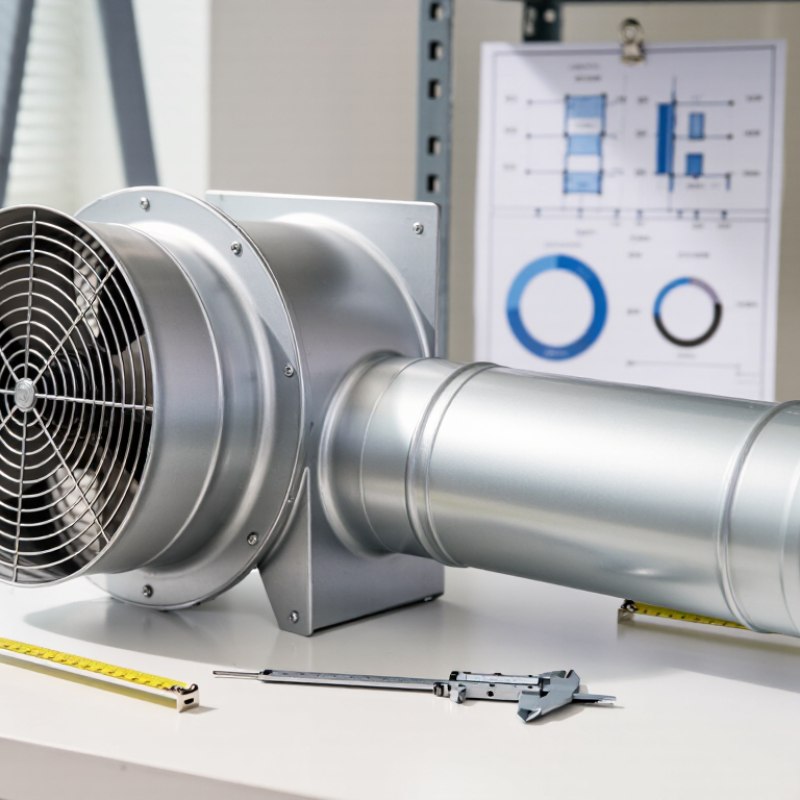
Choosing a cross flow fan starts with the airflow your equipment actually needs, not the largest number on a catalog page. A free-air rating describes output with little or no external resistance. In a real assembly, a grille, filter, narrow outlet, or bend can reduce that flow. Estimate the system’s static pressure, then find the airflow available at that pressure on the fan curve. That matters.
Look for performance data tested in accordance with AMCA 210/ASHRAE 51. These methods provide a standardized way to measure and report fan air performance, making comparable ratings more useful. Check that the curve covers your target operating point, and confirm the stated air density and test conditions. Do not assume a peak airflow value applies once the fan is connected to your housing. Check the curve.
Then account for resistance from the full installation. For example, a dusty filter or a short, tight discharge opening may shift the operating point and lower delivered airflow. A lab rating cannot reproduce every enclosure or installation detail. Still, real ducts differ. Leave reasonable margin for variation, but avoid oversizing without a clear need; excess airflow can add noise or disrupt temperature control. If measurements are available, compare them with the design estimate after installation and revise the assumptions where they miss.
Match Cross-Flow Wheel Diameter and Length to the Available Installation Space
How to Choose the Right Cross Flow Fan?
Match Cross-Flow Wheel Diameter and Length to the Available Installation Space
Start with the space the fan can actually occupy. Measure the cabinet’s internal width, depth, and height, then note nearby panels, wiring, and service access. A cross-flow wheel’s length should suit the width of the air outlet, while its diameter must fit the available depth and housing. Leave room for end supports and the drive; a wheel that fits on paper may still be awkward to install.
Tips: Measure the finished enclosure, not just the design drawing. Check clearances at both ends, and keep a simple dimension sketch for supplier review.
Bigger is not automatically better. A larger diameter may change airflow and pressure performance, but the result depends on wheel speed, blade design, and system resistance. Compare the fan’s performance data with the required airflow and the actual grille, filter, or duct arrangement. Ask for the full assembly dimensions, including motor and mounting points. We once treated a cabinet’s nominal width as usable space; the end bracket forced a small redesign. It was a useful reminder. Allow a little tolerance, then confirm fit with a physical mock-up when access is tight.
How to Choose the Right Cross Flow Fan? — Match Cross-Flow Wheel Diameter and Length to the Available Installation Space
| Typical Installation |
Available Space
(Axial Length × Height × Depth) |
Suggested Wheel Diameter |
Suggested Wheel Length |
Space-Matching Guidance |
| Compact equipment or narrow air outlet |
160 × 70 × 65 mm |
30 mm |
100 mm |
Allows roughly 30 mm of combined axial space for end supports and assembly clearance. Check that the housing and motor fit within the available depth. |
| Small appliance or compact air curtain section |
220 × 95 × 85 mm |
40 mm |
150 mm |
Provides room for end connections and a practical radial allowance around the wheel. Confirm the outlet and inlet openings do not obstruct the airflow path. |
| Medium-sized air-handling or cooling unit |
320 × 125 × 110 mm |
60 mm |
250 mm |
Leaves approximately 70 mm of axial space for supports, drive components, and installation tolerance. Verify the motor location before fixing the wheel length. |
| Wide equipment panel or commercial ventilation assembly |
460 × 155 × 135 mm |
80 mm |
380 mm |
Leaves approximately 80 mm of combined axial allowance. Keep enough clearance for the end bearings or brackets and for servicing access. |
| Long air outlet or large equipment enclosure |
600 × 180 × 150 mm |
100 mm |
500 mm |
Leaves approximately 100 mm for end supports and installation tolerance. Check shaft, bearing, and motor requirements across the full assembly. |
Note: These are illustrative space-planning examples, not universal fan specifications. Wheel diameter and length alone do not determine the complete fan assembly size. Confirm the manufacturer’s housing, shaft, motor, mounting, airflow, and clearance dimensions before installation.
Compare Speed, Pressure, and Power Using Fan Laws: N, N², and N³
A cross flow fan should be matched to the airflow and pressure your equipment actually needs, not chosen by speed alone. Record the required airflow and the resistance from filters, grilles, and narrow ducts. A useful starting point is the fan-law relationship between speed and performance: when speed changes from N1 to N2, airflow changes roughly in proportion to N2/N1.
Pressure changes faster. At a similar operating point, pressure varies approximately with the square of the speed ratio: (N2/N1)². Power demand rises even more sharply, following about (N2/N1)³. For example, increasing speed by 10% may raise airflow by roughly 10%, pressure by 21%, and power by 33%. Small adjustments matter.
These laws are estimates, not guarantees. A dusty filter or a tight outlet can shift the operating point, and motor efficiency may change with load. Compare the fan curve with the system requirements, then check current draw and temperature during testing. Listen for a new hum or vibration. That detail is easy to miss. I would leave some margin, but not assume more speed is always better; the cube relationship can make power rise quickly.
Check Motor Duty and Enclosure Protection Against IEC 60529 IP Ratings
A cross flow fan may run for minutes, hours, or nearly continuously. Check the motor’s duty rating against the real operating pattern, not just the fan’s size. S1 indicates continuous operation under specified conditions; intermittent duties, such as S3, include repeating cycles and rest periods. A duty label alone does not guarantee suitability if airflow is restricted or ambient temperatures are high.
Then check the enclosure’s IP rating under IEC 60529. The first digit describes protection against access and solid objects; the second describes protection against water.
For example, IP54 offers limited dust ingress protection and protection against water splashes. It is not dust-tight, and it is not designed for direct hose jets. Small distinction. The rating applies to the tested enclosure configuration, so confirm whether it covers the motor, terminal box, and assembled fan.
Match the rating to the actual location. A fan above a dry production line may face dust, while one near a washdown area may encounter spray and standing moisture. Higher IP protection can help, but it does not replace suitable materials, drainage, or maintenance.
Check the manufacturer’s test documentation and installation limits, including orientation and cable-entry details. These are easy to overlook. If conditions vary, record the worst expected exposure and operating cycle before choosing; field conditions rarely behave as neatly as a specification sheet.
Verify Sound Levels in dB(A) and Efficiency at the Intended Operating Point
A cross flow fan can look quiet on a catalog page and still become intrusive after installation. Check its sound level in dB(A), then read the test conditions. Was it measured at a stated distance, in a quiet room, with the fan mounted? Without those details, comparisons can mislead. Conditions matter. dB(A) reflects human hearing, but it may not reveal every tonal whine. Listen for narrow, high-pitched tones; they can stand out in a small room.
Judge efficiency at your intended operating point, not at the most attractive point on a performance curve. Match the required airflow and static pressure to the system’s resistance, including grilles, filters, and bends. Record fan speed and electrical input, since performance changes with operating conditions. A fan that moves 200 m³/h against little resistance may deliver less through a restrictive cabinet. Check the curve near your duty point and allow reasonable margin, without oversizing blindly. More speed can increase both noise and power use. Test the installed assembly when possible, at its expected setting and distance. Measurements are imperfect: room reflections and background noise can skew readings. Note them anyway. A small discrepancy may reveal an assumption worth revisiting.