


What potential does the RD signal hold in the context of intelligent control systems for cooling fans?
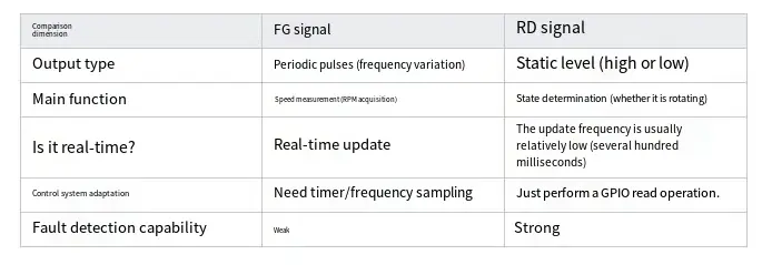
By introducing the RD signal, the system can achieve key functions such as immediate detection of Fan faults and closed-loop feedback for fan control.What isthe RD signal? How does it differ from the FG signal?
✅ FG (Frequency Generator) signal •
Output pulse frequency, used for calculating fan speed (RPM) •
✅ RD (Rotation Detection) signal, which does not represent "whether it is really running" or "whether it is lagging" •
A logic level signal •
Normally, a low level (or high level) is output when the fan rotates normally, and the opposite logic is output when it stops. •
It can be used to determine whether the fan is in normal operation.
By introducing the RD signal, the system can achieve key functions such as immediate detection of fan faults and closed-loop feedback for fan control.
The Four Potentials of RD Signals in Intelligent Control
① Real-time fan operation status feedback (running/stop)
By reading the RD signal status, the system controller can clearly know whether each fan is "actually running", without relying on speed judgment or complex pulse analysis.
Function: •
Determine whether there is a locked rotor or start-up failure. •
Used for device startup self-test (POST) •
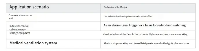
Design an automatic alarm system for fans in case of power failure.
② Support for Fault Early Warning and System Interlock The RD signal can be utilized as a hardware status trigger for fans, enabling interlock with the system's alarm mechanism and power protection mechanism.
Examples are as follows:
In the energy storage Battery Management System (BMS), when the RD signal of any fan indicates HIGH (signifying fan stoppage) ➜ the BMS reduces the load or issues an alarm.
In medical equipment, if the RD signal shows abnormalities ➜ the system interrupts the cooling process.
✅ This approach enhances system reliability and meets the specification requirements for fault response time, such as those stipulated in standards like EN 50178 and IEC 61508.
③ Optimization of PWM Control Strategy for Closed - loop Feedback Realization
When the RD signal is employed in conjunction with Pulse - Width Modulation (PWM) speed control, a dual - closed - loop control system encompassing both rotational speed and operational status can be achieved. Consider the following example:
The PWM is configured to initiate fan operation with a duty cycle of 20%.
The system monitors the RD signal. If the RD signal remains HIGH, it implies that the fan has not started rotating.
The system then automatically increases the PWM duty cycle to 30% and continues this adjustment until the RD signal transitions to LOW.
✅ This approach enables the system to proactively identify the starting point of the fan, optimize energy consumption, and enhance the efficiency of the fan. This not only contributes to the overall performance improvement of the system but also aligns with the requirements of modern academic research in the field of intelligent control systems.
④ Centralized Monitoring of Multiple Fan States for Intelligent Fan Management
In a multi - fan system, multiple RD signals can be connected in parallel to the interrupt input pin or an extended input/output (IO) chip. This configuration enables unified monitoring of the operating states of all fans.
Engineering Practice: How to Interface and Utilize the RD Signal?
Wiring Configuration
Typically, the output is either open - drain (OD) or open - collector (OC).
An external pull - up resistor within the range of 1 kΩ to 10 kΩ should be connected to either 3.3 V or 5 V.
The signal is read via a General - Purpose Input/Output (GPIO) port. A high - level signal generally indicates that the device is stopped, while a low - level signal indicates normal rotation. However, specific interpretations may vary slightly depending on the device model.
Comparison Table of the Advantages and Disadvantages of RD Signals in Practical Applications
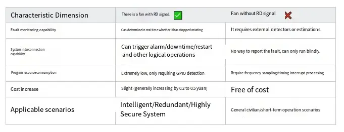
✅ Conclusion: The RD Signal – Endowing Fans with “State Perceptibility”
In an era where the trends of intelligent operation, energy efficiency, and system visualization have taken hold across industries, Cooling Fans are no longer simply “mechanical rotating devices.” Instead, they have evolved into intelligent actuator components that demand feedback, possess predictability, and are amenable to management.
The introduction of the RD signal imparts digital information regarding “operational status” to fans. Its advantages include:
✔️ Real - time Visualization: Facilitates immediate and intuitive understanding of the fan's operating state.
✔️ Simplicity in Readability: Allows for straightforward interpretation of the information it conveys.
✔️ Ease of Inter - connectivity: Enables seamless integration and interaction with other components within the system.
✔️ Marked Enhancement of Safety and Maintainability: Contributes significantly to the overall safety and ease of maintenance of the system.